Adding Heating to the IceMaster Max 2
My glycol chiller includes two-stage temperature controllers. With just a little bit of work, I was able to expose this capability and add a heating circuit for my fermenter.
As part of my move to a ten-gallon brewing system (more on this later), I recently purchased a 14 gallon unitank from Ss Brewtech. This thing has all of the bells and whistles, including lid-mounted coils for temperature control. I also purchased a glycol chiller, the recently-introduced, relatively-inexpensive, and right-sized BrewBuilt IceMaster Max 2.
A later post may go into the decision process that led to buying this fermeneter. But one motivator was that this is capable of anything I’ll ever need to do: harvesting yeast, pressure fermentation, carbonation, even dispensing. It’s a lot more than any homebrewer needs to make good beer. Suffice it to say, working at the brewery last year did instill an appreciation for professional equipment.

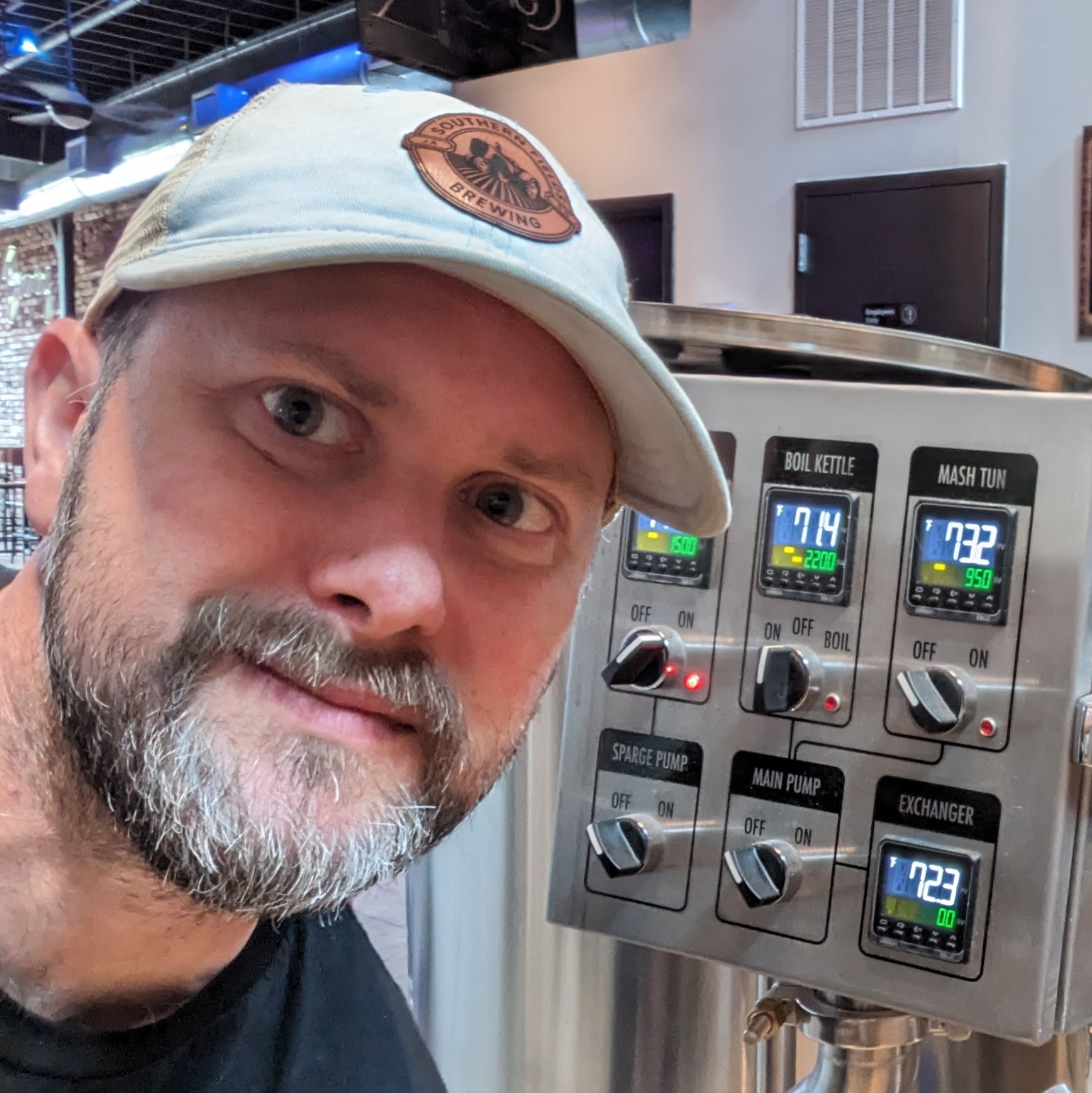
My short-lived career as an assistant brewer.
One of the benefits of the latest IceMaster Max 2 (also known as the IceMaster G20.1) is that the built-in controllers are dual-stage. This means that I can use the same controller for both the cooling circuit (which pumps from the chiller’s reservoir through the fermenter’s coils) and the heating circuit (which powers the FTSs² heating pad). This is beneficial for a number of reasons, the main reason being that if I used a separate controller (e.g., the one that came with the FTSs²), they could potentially both run at the same time. If at all possible, I’d like to reserve distributed consensus and control problems for working hours and keep them out of the brewery.
The manual provided by KegLand.au helpfully includes instructions for wiring a heating circuit against the temperature controllers, with a wiring diagram. Interestingly, the instructions provided by BrewBuilt to MoreBeer don’t include these instructions; maybe they trust the Australian customers more than they trust the Americans?
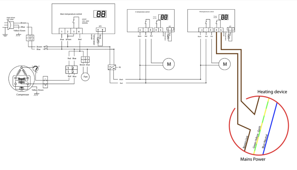
Wiring diagram for the G20.1 controllers.
Anyway, the solution is as simple as using the heating relay on the controller to switch the heating circuit. I opened up the two-stage controller that came with my FTSs² heating package and verified that the heating pad just needs 12 volts DC. I hoped that I could use the same 12 volt circuit in the glycol chiller that powers the controllers and the pumps. The laptop-style AC/DC inverter included with the FTSs² outputs 8A at 12V, but the FAQ at Ss Brewtech says that the heating pad only uses 60W (so, 5A at 12V). The IceMaster manual didn’t indicate how much power was available, but peaking through the vent at the back showed the inverter, which unfortunately was rated for only 2.5A.
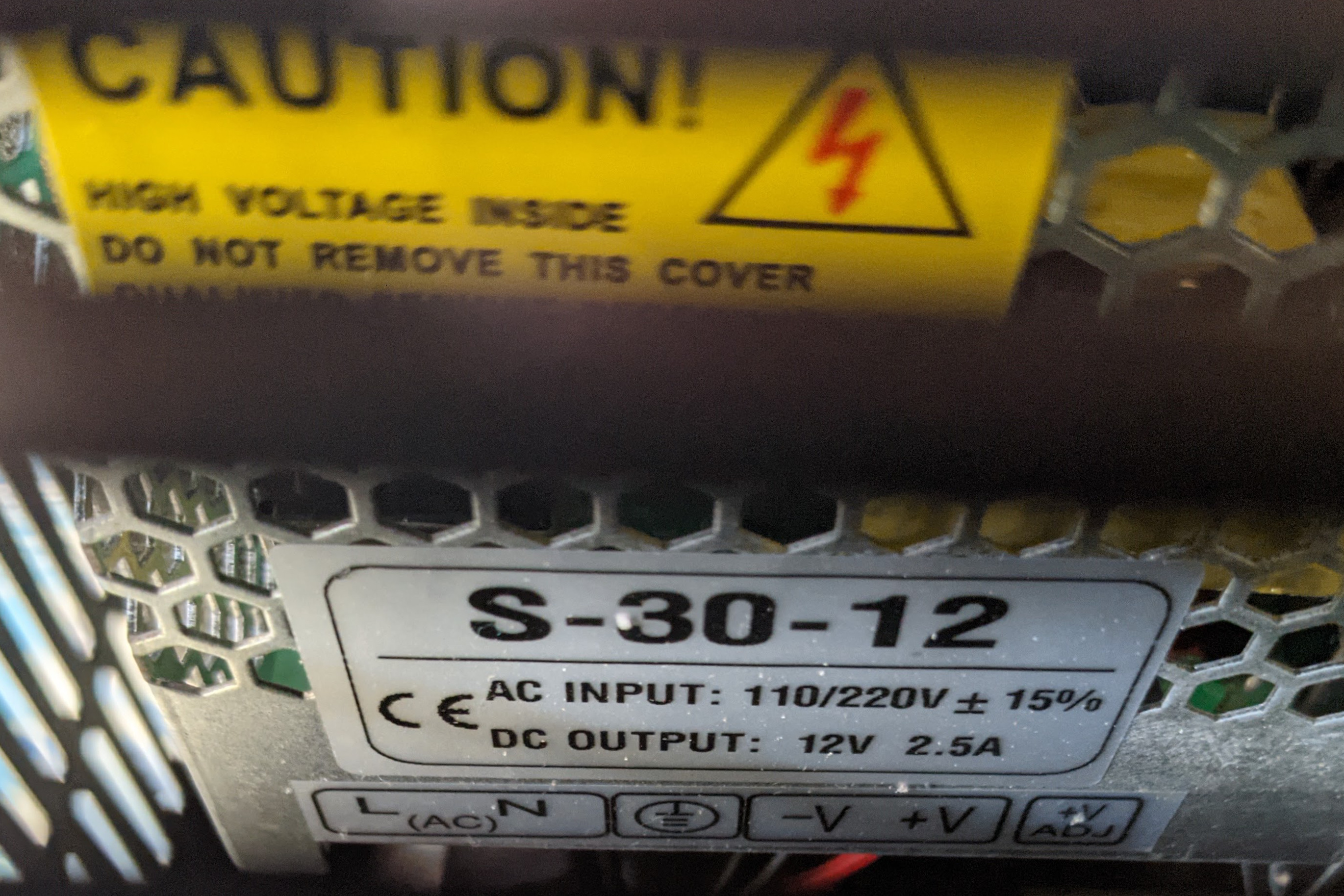
Scotty, I need more power!
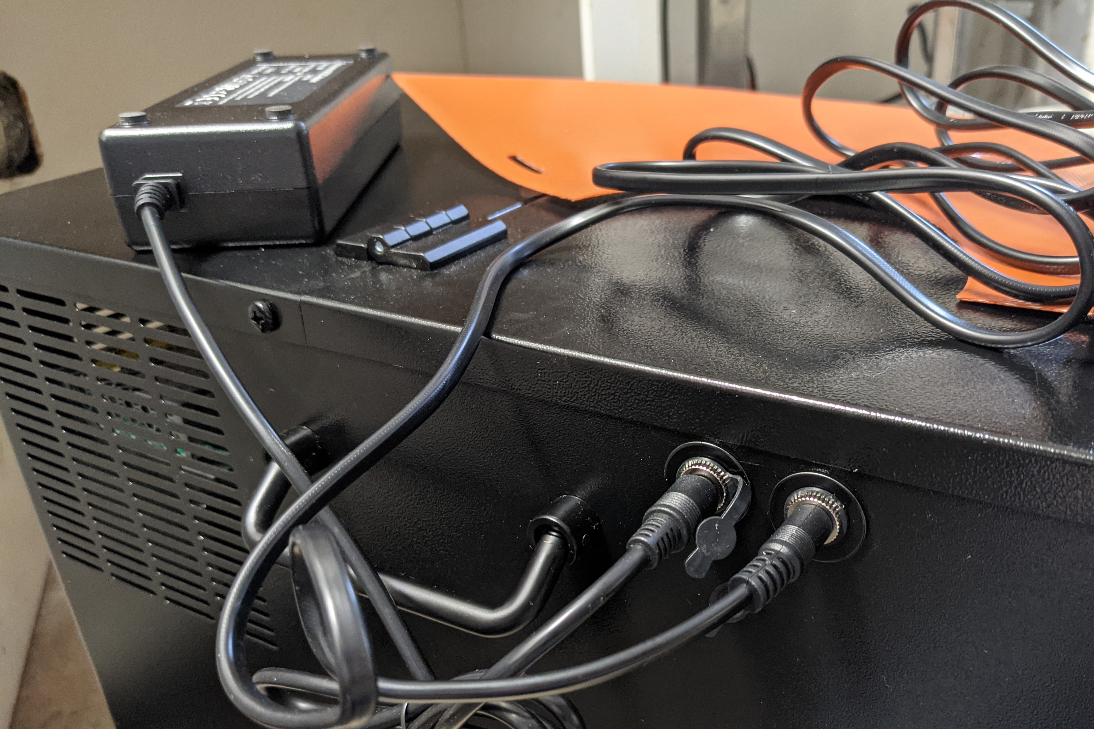
As a result, I’ll need to use an external power supply, and I need the relay inside the IceMaster inline between the power supply and the heating pad. I had the power supply that came with the heating pad, I just need to wire it and the pad through the relay. I didn’t want to do any more surgery on those than I had to; fortunately, both are equipped with DC barrel plug. I measured them and ordered an appropriately-sized and power-rated panel-mount sockets.
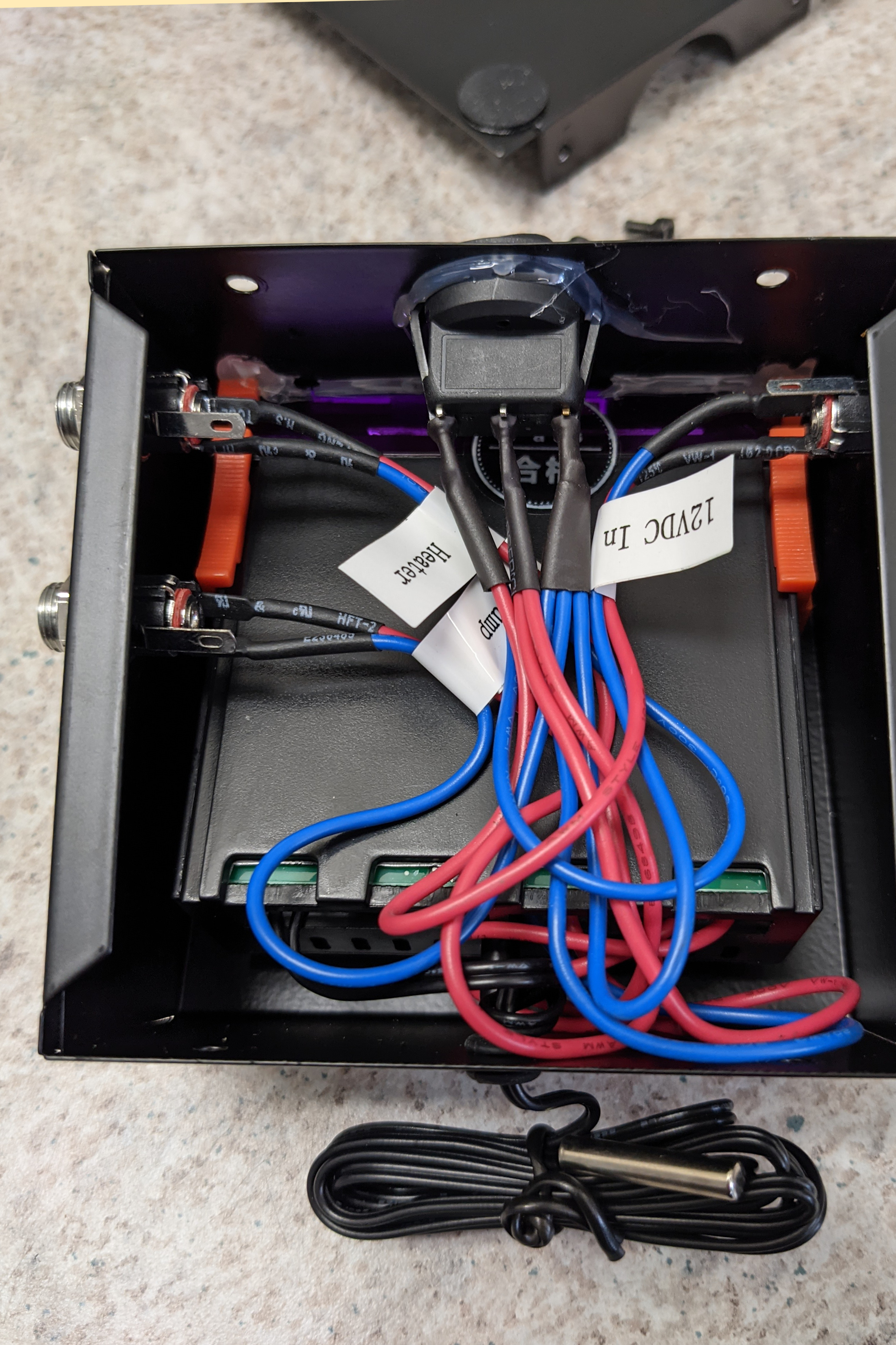
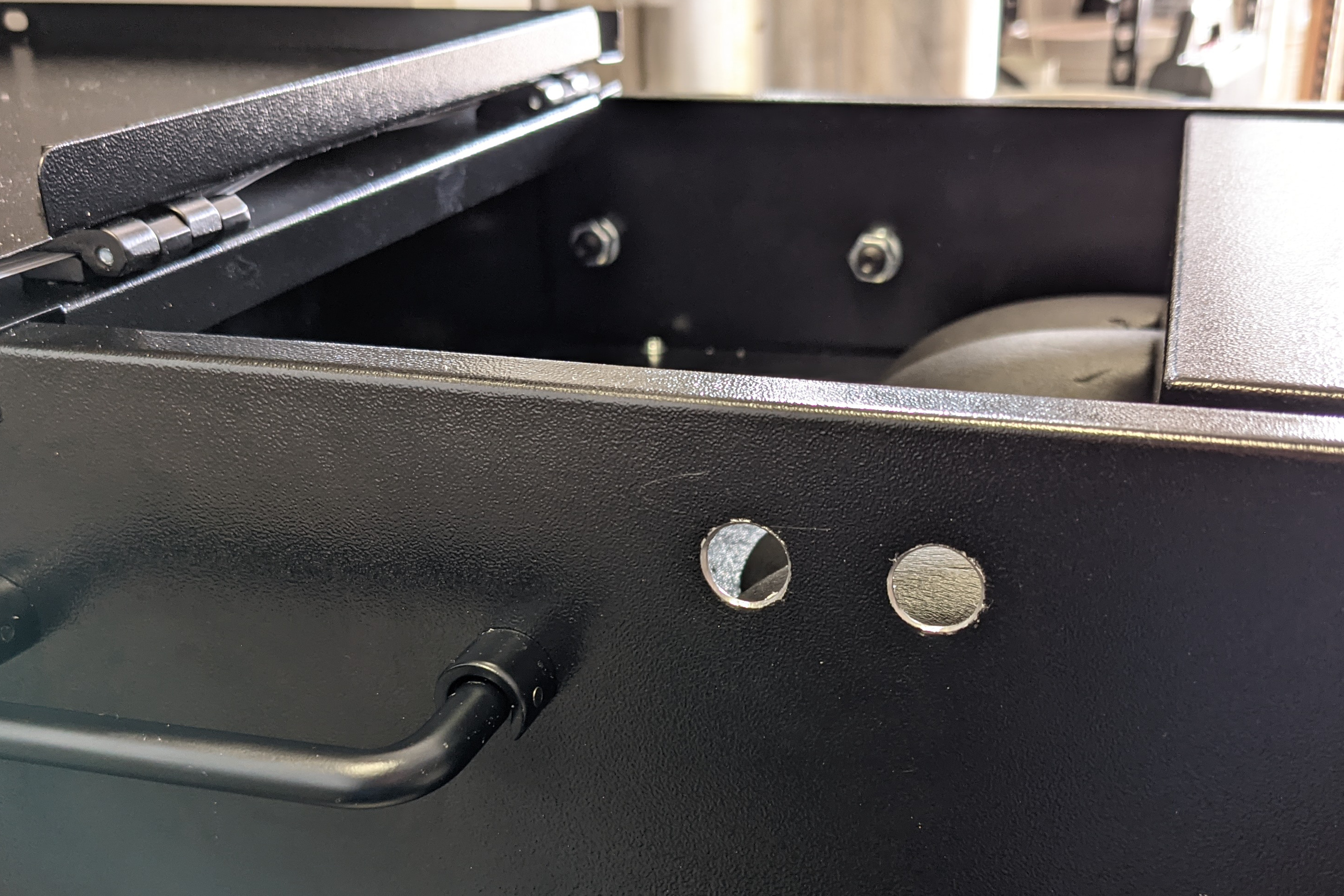
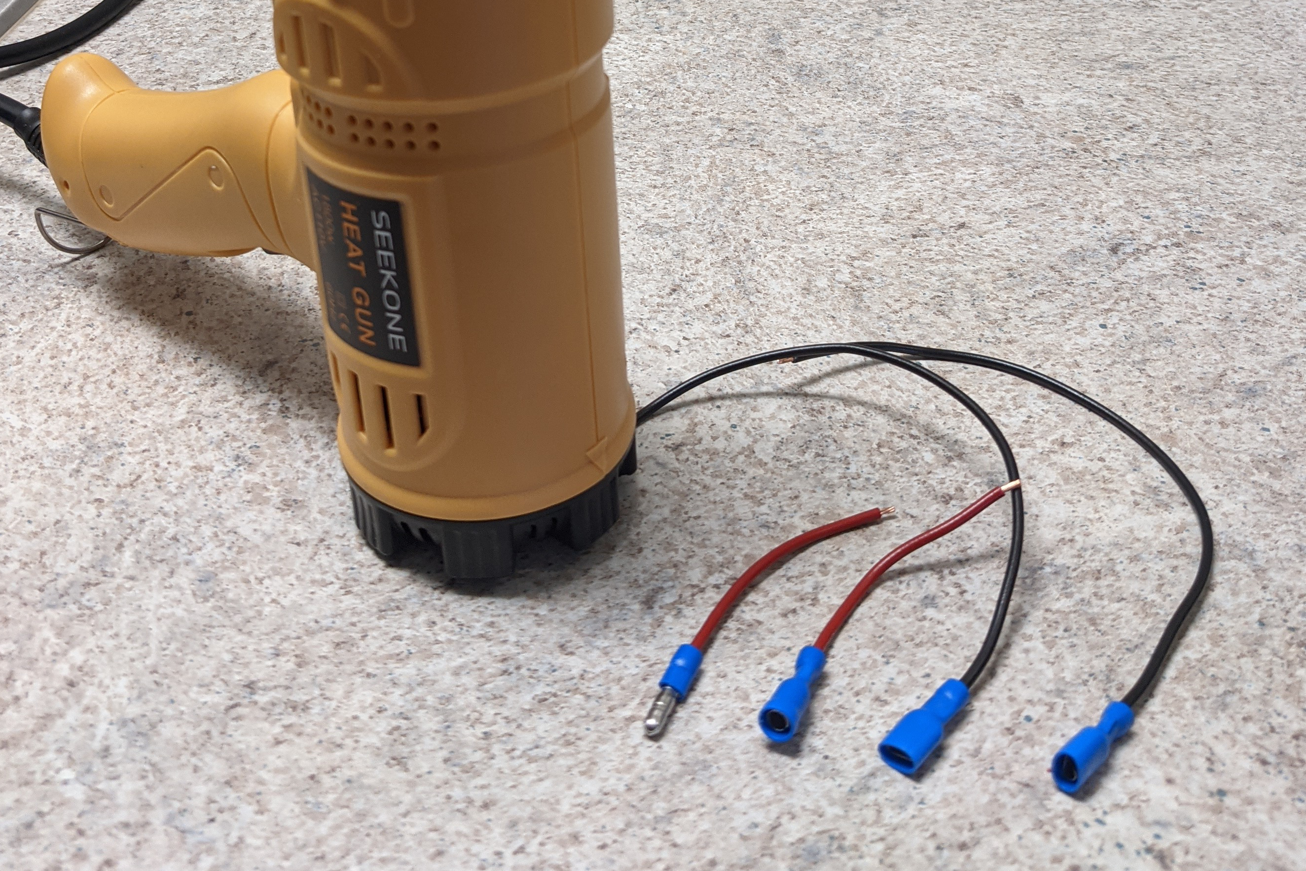
I drilled holes in the side for the jacks. (Tip: put a plastic bag or something inside the electronics compartment to catch the metal shavings from drilling the hole and tape over the fill hole into the reservoir. I didn’t, and I had a mess to clean up as a result. Also, the mounting hole diameter needs to be 11mm; I went too far on my step bit and ended up having to invest in a few washers.) I had a collection of crimp-on connectors; I put blade connectors on the negative line to attach to the blades on the relay, then a pair of matching connectors on the positive line. This allowed me to do all of my soldering outside of the case; I’m bad enough at soldering in un-cramped circumstances.
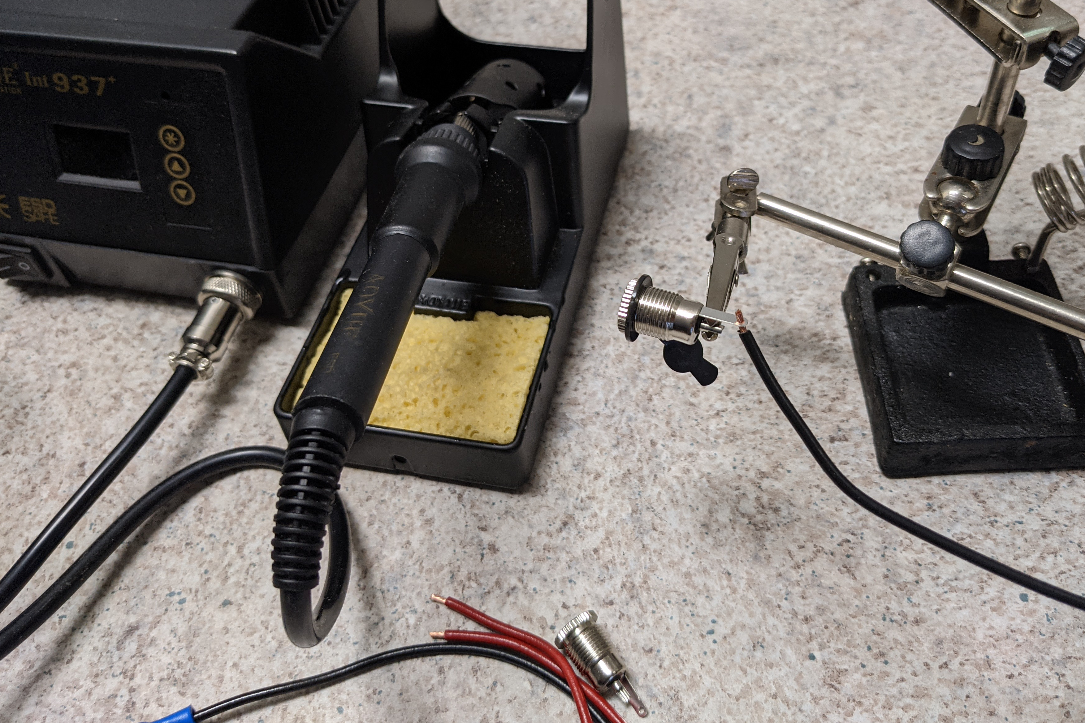
Soldering the connectors the first time.
I installed the jacks into the case, attached the positive line connectors, and attached the negative lines to the relay. I turned on the master power supply for the chiller, changed the controller set point to a high temp, and verified that I had continuity between the jacks on both the positive and negative lines. Then I lowered the set point, heard the relay click, and checked to find that… I still had continuity across both lines 🙁. I unplugged the negative lines from the relay and still had continuity, so I knew it wasn’t a defective relay. I checked my shoddy soldering and verified that I didn’t have a short between negative and positive (that would have been exciting), and I realized it had to be the case. Unfortunately, the barrel jacks I bought are only two-pole, with the “outside” pole connected to the body of the jack… which was connected to case. The result is that I had a closed circuit on the negative line through the case, independent of whether the relay was engaged.
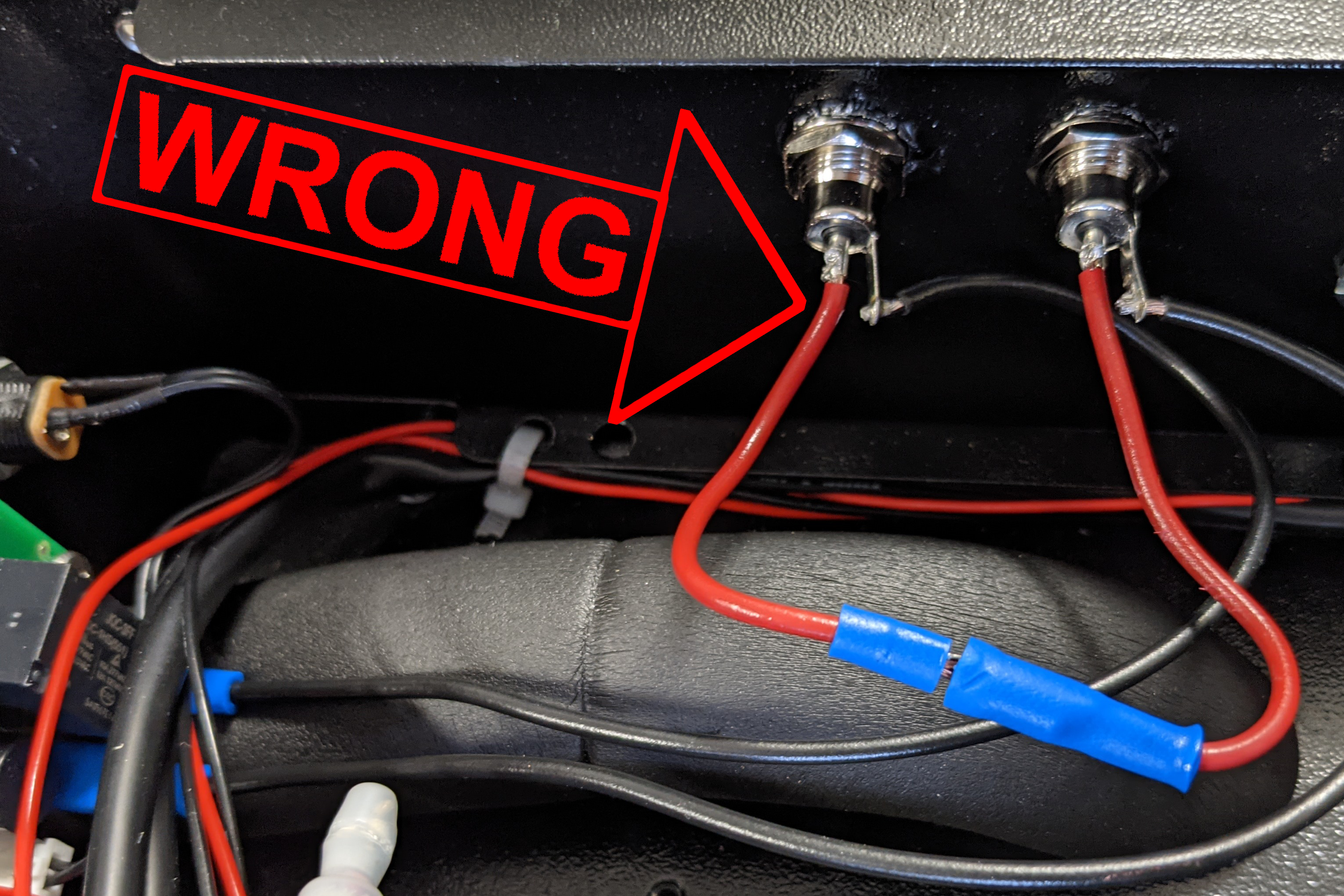
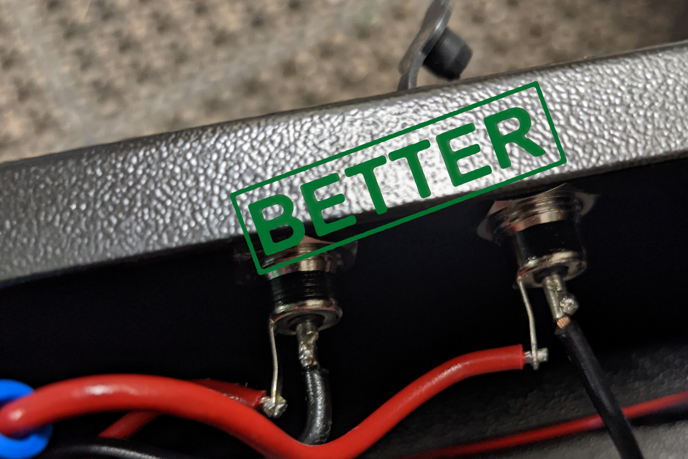
This is the correct way to wire these jacks if you want a closed circuit through the panel.
So, my only choice with these connectors was to switch the center (positive) line on these jacks through the relay, leaving the outside (negative) constantly closed (through the case and a jumper). I disassembled, desoldered, resoldered, and reassembled. I didn’t want to to have to recrimp the connectors, so I reused the existing wires. This means that black is positive and red is negative; I’m sure that won’t come back to bite me later on.
Don't judge my solder joints.
Everything tested out fine with the multimeter, and then with the power supply and the heating pad. The result is a clean build; I didn’t have to cut apart the factory connections on anything, and the whole thing may even be code. Not that I care about code; what am I, Australian?